How to Use SD540C and CANLight with LabVIEW
This blog post will guide you through programming your CANLight and SD540C devices from LabVIEW.
Updating Your roboRIO
WPILib has some fantastic documentation on setting up your roboRIO and development environment. Getting Started with the 2017 Control System is a great place to start. Make sure you have the latest FRC LabVIEW updates and the 2017 image on your roboRIO before continuing.
Installing the Library
You will need to download the mindsensors FRC library for LabVIEW. Extract this .zip archive, it contains the new VIs for your LabVIEW environment.
Navigate to the following folder, or the equivalent if you have installed LabVIEW elsewhere: C:/Program Files (x86)/National Instruments/LabVIEW 2016/vi.lib/Rock Robotics/WPI/ThirdParty. In mindsensors_LabVIEW.zip you will find a folder similarly named ThirdParty. Copy it over.
The mindsensors Configuration Tool
The mindsensors Configuration Tool can be used to change the parameters of your SD540C and CANLight devices. For the SD540C this includes changing the ID, name, limit switch settings, invertedness, and stop behavior. For the CANLight it also features a live-updating color test mode. The mindsensors Configuration Tool will also allow you to update firmware. Read more on how to download and use this tool on our blog post.
You must successfully run this tool at least once to get the mindsensors FRC library on your roboRIO. You will not be able to use the mindsensors VIs in LabVIEW if the mindsensors FRC library is not on your roboRIO.
Running an Example Program
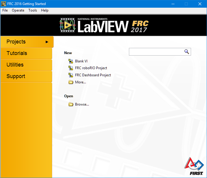
Go ahead and open up LabVIEW! Or, if you already have it open and just added the mindsensors VIs, restart LabVIEW.
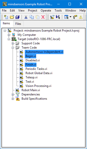
Here is a project containing eight examples, four each for the SD540C and CANLight. Below you can find a description of each example VI. Further examples may assume basic knowledge from the previous examples, so we suggest you go in order.
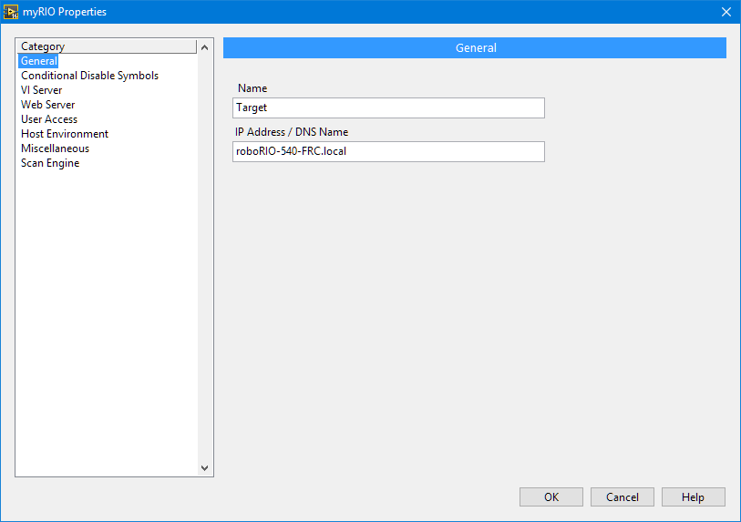
Be sure to change your team number! Right-click "Target (roboRIO-540-FRC.local)" and select Properties. In the "IP Address / DNS Name" field, update the text box with your team number.
Double-click a VI in the Project Explorer to open it up. Here you can see the front panel.
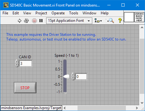
There is where you can interact with the VI. Hit Ctrl+E to open the block diagram (or use Window -> Show Block Diagram).
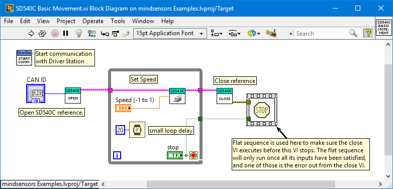
Here you can see the "code" that makes the VI run.
To execute a VI, click the white arrow on the left of the toolbar (on the front panel or block diagram), or use Ctrl+R, or Operate -> Run, right-click the VI in the Project Explorer and select Run. Many options!
It may take a minute to connect to the roboRIO and copy over all the VIs. If it fails to connect please check your team number is set correctly and the roboRIO has an active connection to the computer running LabVIEW. If another LabVIEW project is currently open and connected to the roboRIO, a second project will not be able to connect at the same time. You can right-click "Target (roboRIO-####-FRC.local)" and select Disconnect on the other project. You may see a warning if you already have Java or C++ code running on your roboRIO.
Keep in mind that the Driver Station must have Teleoperated, Autonomous, or Test mode enabled to allow an SD540C to run. Even though we are running a single VI as an example and don't have separate code for each mode, it is still required for safety. Examples that use joystick input, such as SD540C Joystick.vi, will not work correctly under autonomous mode (joystick input will be blocked).
SD540C Basic Movement.vi

This is the most basic set of blocks to make an SD540C move. We open a reference, repeatedly set its speed, and close the reference once the stop button is pressed. We also start communication with the driver station, but only once (outside of the loop). There is a twenty-millisecond delay in the loop so we don't bombard the roboRIO with data. The CAN ID and a slider for the Speed are on the front panel. The loop reads the value of the speed slider and uses it as the input to the Set VI.
The structure that looks like a film strip around the stop sign is flat structure sequence. As you may expect, the Stop block will stop this VI. However, we want to make sure we close the SD540C reference before the VI stops. LabVIEW is a dataflow-based programming environment. A VI will only run once all of its inputs have been satisfied. This is why the VI to begin communication with the Driver Station runs right as the example VI begins, because it doesn't require any inputs. Because the flat sequence has a tunnel for the loop boolean and the Close VI's error out, it will not run until the loop ends and Close finishes. Even though it doesn't do anything with the Close VI's error out, it still requires that data before being able to Stop. Pretty cool!
SD540C Joystick.vi

Now we introduce a joystick to this example. As before, use use an Open VI to get a reference to the joystick, call the Get Values VI repeatedly, and finally use the Close VI when the loop is done. The joystick close VI's error out is not wired to the flat sequence around stop because it is not essential. Unlike the SD540C, where you must call the close VI or it will not run again until you restart the roboRIO.
Instead of a 20ms delay, we use this strategy with an occurrence to only run the loop when there is new data from the Driver Station. We do include a one second timeout, so the loop will run at least that often. There is no point in calling it when there is no new joystick data, however.
The Get Values joystick VI outputs an array of doubles for the different axes. We use an Index Array block to get the individual values out, skipping the first one (x-axis) and using the y-axis value. This is already between -1.0 and 1.0, so we don't need to scale it before passing it to the Set SD540C VI. There is also an indicator on the front panel to visually see the current joystick value.
SD540C Coast.vi
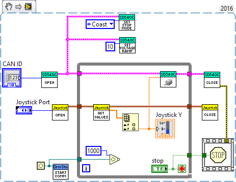
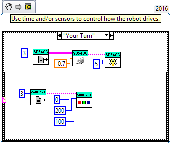
Very similar to before, only now we configure the SD540C a bit (one time at the beginning, not inside the loop!). We set the stop mode to Coast instead of Break. We also set a positive voltage ramp (details below). This can be useful to make the robot drive more gentle for rookies driving the bot for the first time. Note that stop mode and voltage ramps are controls in the VI you download, so you can more easily change them. I only used the constants Coast and 10 here to make it easier to visualize.
The voltage ramp setting with ramp up the motor when it is set instead of instantly going to that value. 0 (default) will instantly start moving the motor at the new speed you set, while a larger value (up to 255) will give you a smoother change in speed.
SD540C Limit Switches.vi

The SD540C has built-in support for limit switches. This program gives you an example of how to use them. Please keep in mind this is an example and may require modification to suit your team's needs. For more information about the concept of using limit switches, read our blog post All About Limit Switches. This example uses some VIs to configure the SD540C before the loop starts. Note these settings are stored on the SD540C and will be remembered between power cycles. The may also be set using the mindsensors Configuration Tool.
This loop is somewhat similar to the previous examples. However, here we are choosing an action based on the state of some buttons, not a joystick axis value. As such we wire the buttons array instead to the index array function. You can expand this function vertically to select more individual values. Because there are many more buttons, we use some constants to specify which index we want. On our joystick 4 and 5 correspond to the left and right bumpers. We wire these to a pair of indicators so we can easily verify the VI is receiving input correctly, and to a case structure we'll get to in a minute.
In this simple example you can imagine the SD540C moving an lift. There is a limit switch positioned at the top and bottom of the lift. To stop the lift from moving too far, we enable limit switches on the SD540C. If it moves forward (up) so far that it bumps the limit switch, it will not move further. This functionality is built in to the device, no programming required. We configure the forward limit switch as normally open, so it will stop moving when the switch is closed or activated.
That limit switch functionality is built in, but we still need to move the lift up or down depending on which bumper is pressed. The left bumper boolean values is wired to the outer case structure. If it is true (the left bumper is pressed), the Set VI will be called with a constant of positive 0.5 to slowly lift the lift. In the false case, we then use another case statement to check if the right bumper is pressed. If so we Set it to a constant value of -0.5.
The solid green square where the right bumper values passes through the outer loop is called a tunnel. This will not affect the true or false value of the outer case structure (that is wired to the left bumper), but it makes this value available for use inside either case. In the true case we ignore it, but it is used in the false case. We also use a tunnel to get the SD540C reference inside the case statement.
At the moment this will act as a toggle. Pressing the left bumper will cause the lift to rise even after it is released. How might you make it stop when released? The answer is in the next sentence. In the false outer case and false inner case (neither button is pressed) use a Set VI with the constant 0.
CANLight Basic Color.vi
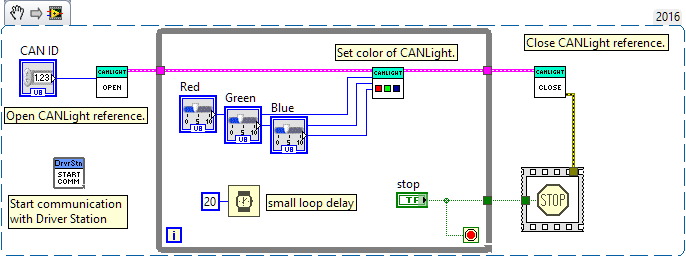
Parallel to SD540C Basic Movement.vi earlier, this is the simplest way to set the CANLight to a static color. The description of that VI applies almost exactly here. Notice the three controls for red, green, and blue use the data representation "U8" for unsigned byte. It takes a value between 0 and 255 (2^8-1) for each color.
CANLight Demo.vi

This walks you though all of the methods provided in the CANLight library. It also introduces the concept of the CANLight's color memory bank. The CANLight has a set of 8 registers. Each stores a color and associated time value. For much more detail on the CANLight see our Getting Started with CANLight presentation.
The overall structure of this VI looks intimidating only because there is an example of every main CANLight VI on one screen. You can focus on the inner part of each case structure for the example of each VI. If you do want to understand the entire block diagram, it works as follows. A tab control is used on the front panel to separate out the controls. These all show up in the same block diagram, creating many buttons and numeric inputs. There is a single large loop in the center. It has several case structures, each checking if a specific button was pressed. These buttons are set to latch when released (right-click the button on the front panel -> mechanical action). This means they will only be true for a moment when they are released. This is why we use a greater 100ms delay for the loop, you certainly shouldn't need to click a button in this example more than ten times each second. Each false case is empty, but when the button is pressed the true case will run the intended example. Each contains a single CANLight VI (Blink LED, Set Color, Write Register, etc.). These need a reference to the CANLight we are using, so that is passed in through a tunnel (the same CANLight and reference are used for every example). Then each simply has its corresponding controls wired to the CANLight VI.
CANLight Match Alliance.vi
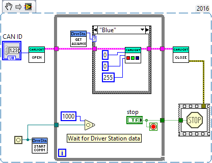
This small but fun example will change the lights' color to match your robot's alliance. You can change your team's position in the bottom-middle of the driver station, labeled Team Station. Again we are using a delay to wait for the driver station instead of a timed delay because we only need to update when there is new data from the driver station. The Get Alliance VI will return red or blue (and also your position, 1 through 3). We simply use a case structure and a different set of constants for the Set VI depending on which alliance is found.
CANLight Custom Flashes.vi
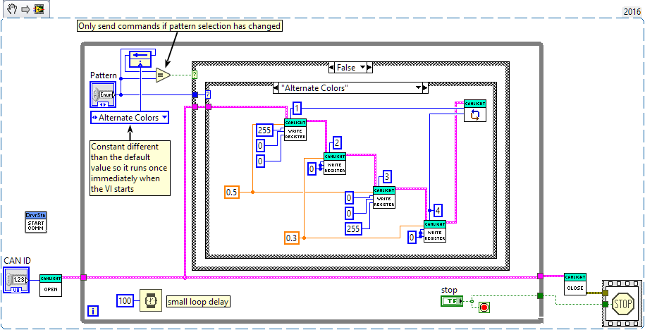
If you want to use some more involved flashing patterns, this gives you an example of how you might do so. Don't be intimidated by the outside code, only what is inside the inner-most case structure ("Alternate Colors" etc) is what you will need. Use the Write Register VI for each index you want to write to, and specify the red green and blue, duration, and what index to write to. The CANLight reference is passed through sequentially to make sure that the Write Register VIs are executed before the Cycle, Flash, or Fade VI.
The outer structure is in place because this inner structure should only be called once. You don't need to call Write Register and Cycle 50 times a second, just call it once and it will continue until you give it another command. In fact, if you do keep calling it, you may only see a single color because the cycle is starting over so quickly. The outer code ensures the inner code is only run once each time you change the value of the Pattern control. A feedback node is used to compare Pattern to its previous value. If they are not equal (the selection has changed) then the inner code will be executed. If you prefer you could use a shift register instead.
It may also be worthwhile to take a look at the .java/.cpp equivalents of these files to get a general idea of these devices are used in text-based programming languages.
Working with a Full FRC roboRIO Robot Project.lvproj
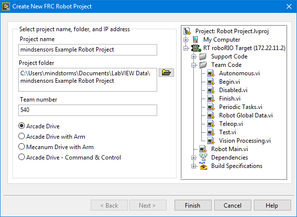
Click New "FRC roboRIO Project."
It may take a minute to configure the project and load all the VIs it needs. On the next dialog give your project a name and fill in your team number.
If you open up the Team Code folder in the Project Explorer, you can see all of the VIs that the new FRC robot project came with. For this example we will be modifying Begin.vi, Autonomous Independent.vi, and Finish.vi.
Begin.vi
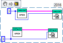
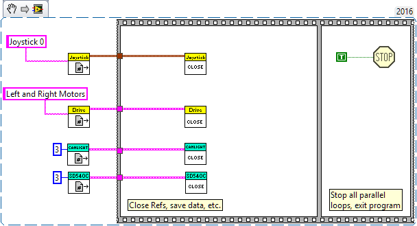
As before we use the Open VI to get a reference to the mindsensors CAN devices. There's a problem though. We need to use these references in Autonomous Independent.vi, but how are we going to get this wire between VIs? Luckily, there is a Set Reference VI in both the CANLight and SD540C function palettes. Use these to store the reference so you can retrieve them later. Notice it also takes in a number for the ID where you want to set this reference.
Autonomous Independent.vi
Now that we want to use those references, we use the Get Reference VI! Just specify which ID you want to get. Now you have a reference you can pass to any other VIs that need them. Remember to use this system of setting and getting references, you can't call Open.vi multiple times.
Finish.vi
When your robot program ends, we need to close these references so we can make new ones the next time your program runs without issue. Get any references you have opened and pass them to the Close VI. You can use the joystick and motor drive VIs as an example.
Conclusion
We hope you have fun using these devices! You can find a full list of available methods in the Java and C++ documentation. Feel free to post in the mindsensors.com forum if you need help, or Chief Delphi if you are new to FRC. Good luck in the 2017 season!

