
PiStorms Frame Assembly
The PiStorms Frame is designed to house a PiStorms, Rapberry Pi, and battery pack. There are holes on both sides of the PiStorms Frame to allow for easy connection of LEGO MINDSTORMS parts.
IMPORTANT: assemble this frame first and affix your Raspberry Pi in this frame before you attach PiStorms board.(The devices will be damage if PiStorms is not connected correctly to Pi on GPIO pins,The frame helps establish correct connection on GPIO pins). |
Which Frame do you have?
If the frame you have is Black colored, molded frame, follow these steps. If your frame is 3d Printed Lavender/Blue colored, please scroll down to 'Mounting your Raspberry Pi' section.
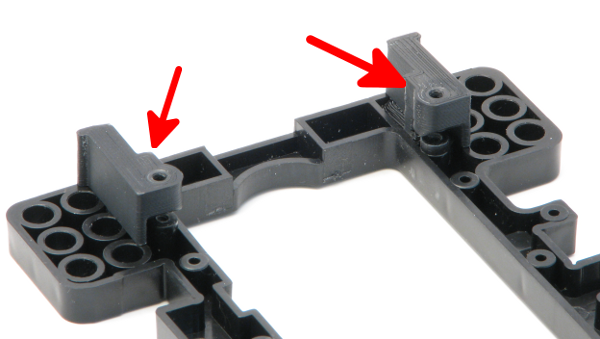
Assemble the Guide Caps
Attach the Guide Caps on the center piece of the frame as in picture below:
(If your Guide Caps are connected to each other, snip off the connectors and separate the Caps).
Mounting your Raspberry Pi
If your frame is 3d Printed, the Guide Caps are already built in, simply mount your Pi in the 3d Printed frame.
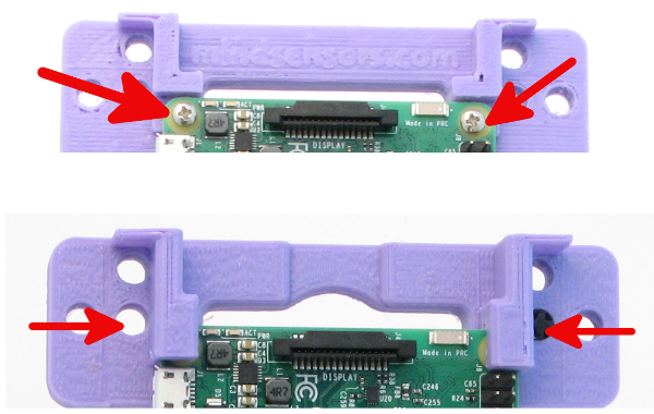
Notice the different Frame designs in picture above. One design has screws to mount the Pi, whereas other design has slots to insert the Pi.
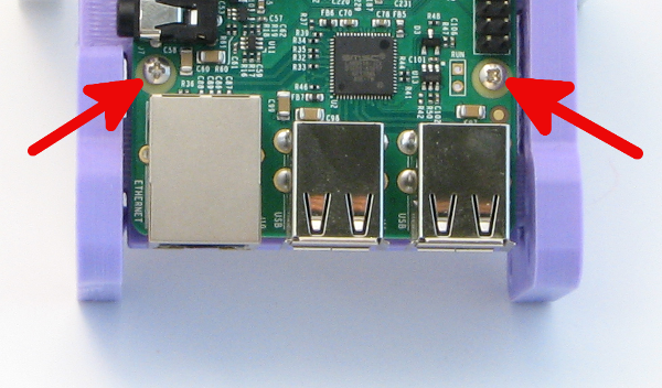
Whichever your design is, the bottom edge of Pi is secured with screws (as in picture above). Be sure to line up the Raspberry Pi and screws correctly with their respective holes before you fasten them. If your design requires 4 screws, be sure to fasten them all correctly.
Mounting Pi on Molded Black Frame
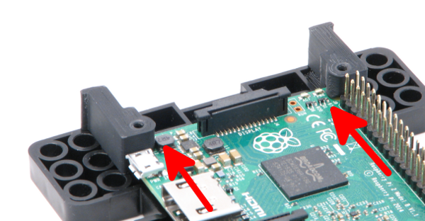
Insert the Pi between the Guide Caps and insert the 1/2" long screws from top.
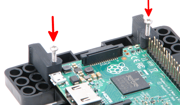
Insert the 1/2" screws and fasten the screws with a screw-driver:
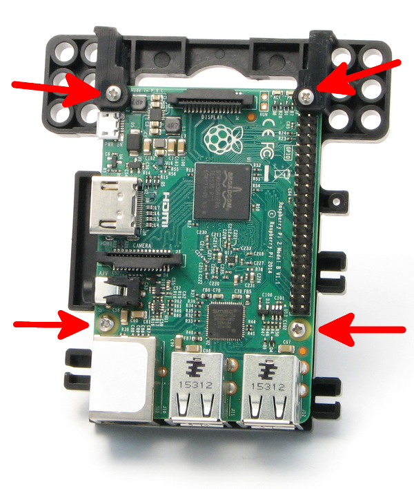
Be sure to secure the bottom edge of your Pi with screws.
Your assembled Pi will look like this:
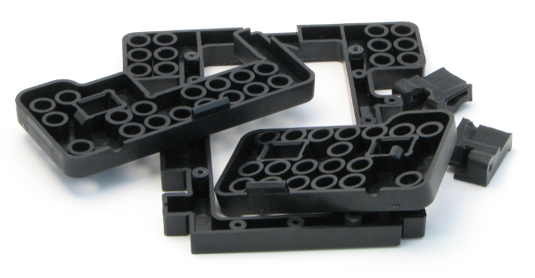
Assemble remaining plastic pieces
The three main frame pieces will connect as follows:
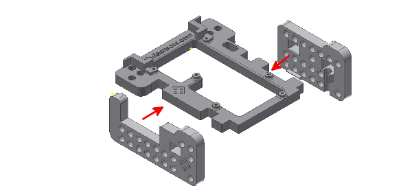
Note how the pieces will be fitting together. Firmly press the side pieces onto the center piece.
Attaching Power for PiStorms

If you are using Rechargeable battery pack, follow these instructions |
From the back flat side of the back piece, run the wires of the battery pack through the rectangular slot next to the Raspberry Pi GPIO pins.
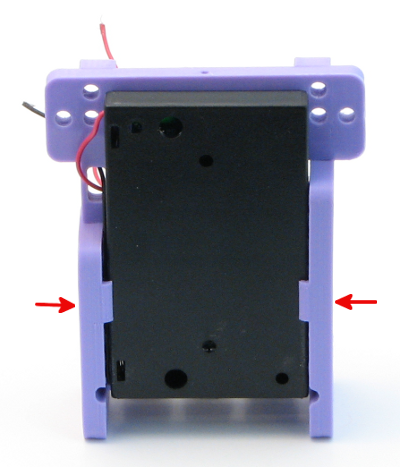
Slide the battery pack to into place so that it is held by the notches on the left and right piece, as seen in the picture above.
It is recommended that battery box be fitted with batteries facing back (as in picture above).

Connect the battery pack wires to the green power connector on the Raspberry Pi. Pay close attention to the polarity. If your battery pack is hooked up incorrectly, there could be permanent damage to the PiStorms and/or Raspberry Pi upon startup.
Note: On this battery Pack, Red wire is connected to +ve terminal, and Black wire is connected to -ve terminal. |
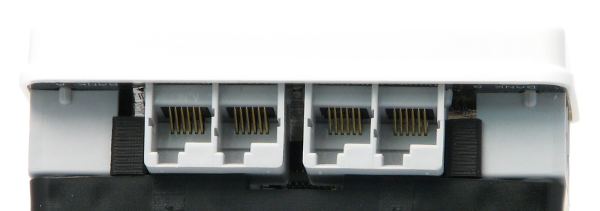
Connect your PiStorms to the Raspberry Pi by inserting the GPIO pins into the black connector on the Raspberry Pi. The sensor port connectors should be inside the Guide Caps at the top of the back piece, as seen in the above picture. Ensure the PiStorms and Raspberry Pi are connected correctly. Incorrect connection will cause damage to the PiStorms and/or Raspberry Pi upon startup.
Insert 6 AA batteries into the battery pack and press the button to power your Raspberry Pi.
Have fun creating robots, games, and projects with PiStorms!

