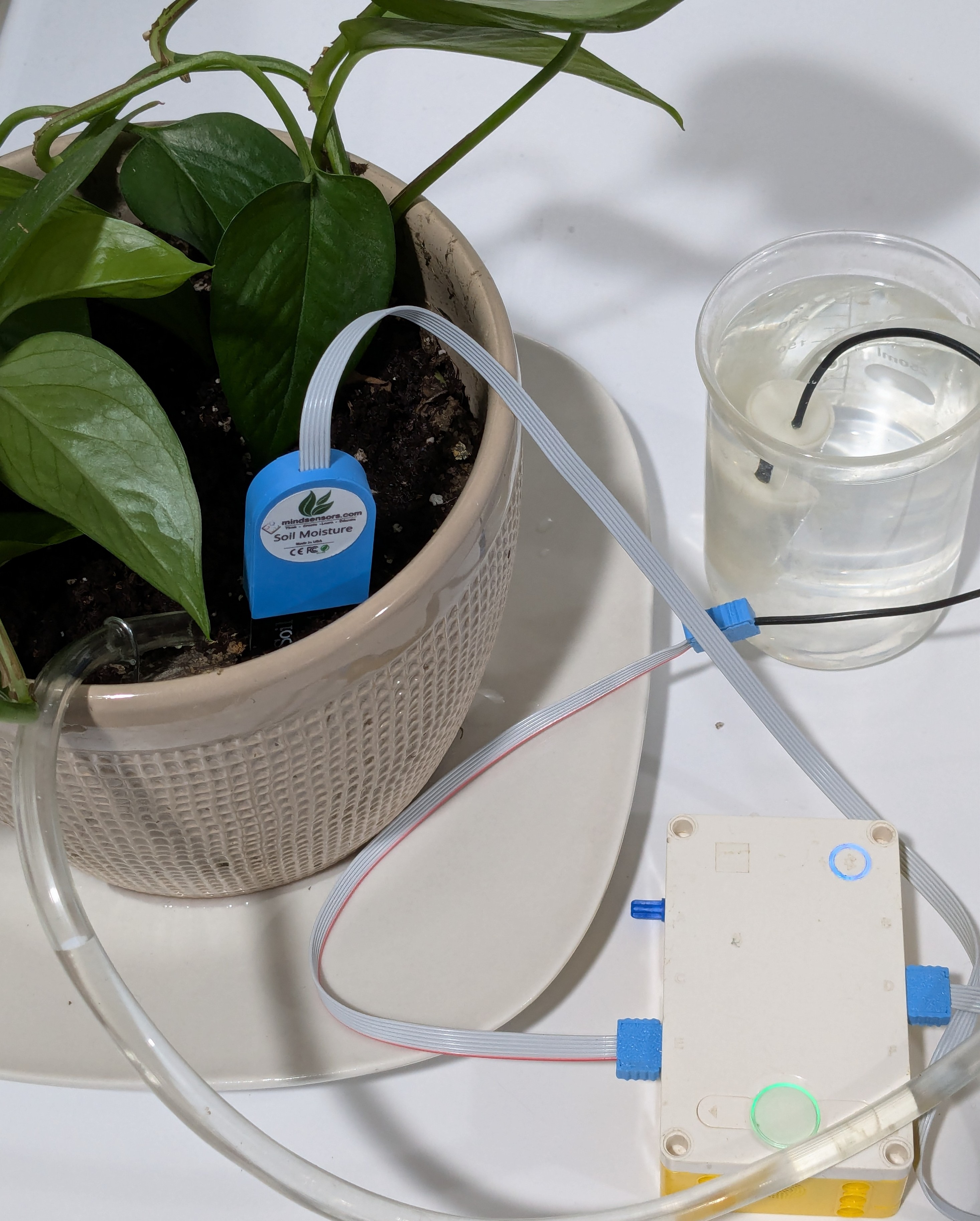
Keeping plants healthy isn’t just about giving them water — it’s about giving them the right amount at the right...

LineLeader vs. LightSensorArray
Introduction
Building a line following robot can be a fun project as long as you have the right sensor. mindsensors.com offers two sensors to get the job done. Both are basically an array of light sensors that will help your robot monitor the location of the line.
Physical Comparison
At first glance, the LightSensorArray and Lineleader (Line Follower Sensor) are very similar. Both sensors have the same size, shape, and weight. They both have an array of 9 LEDs to provide a stable light source, and 8 light sensors to accurately sense the location of the line. The only visual difference between these two sensors is the color. The LightSensorArray is black, and the Lineleader is red.
Calibration
There is absolutely no difference in the calibration process of these two sensors. For best performance, calibrate the sensor so that the target is the same distance as the line that will be tracked. It is best to re-calibrate these sensors if the ambient light source (any light not supplied by the 9 LEDs of the sensor) changes.
Seeing the Line
Both the LightSensorArray and the Lineleader see lines the same way. The array of LEDs will shine light on to a target. The 8 light sensors will then read the light reflected of the target. In a normal line following situation, the outer sensors on either side will see white (high value), and the middle sensors will see black (low value). If the black line starts to fade over to one side, the black will show on different light sensors. The sensors will send this information to the robot and the motor power will change to keep the black line in the middle.
Software Comparison
When the sensor sees the line, the information is input into what is called a PID algorithm. This will perform some math (calculus) and tell the motors exactly how much to correct to keep the line in the middle. The LightSensorArray and the LineLeader handle this PID algorithm very differently.
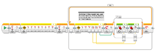
The LightSensorArray will read back the value of each of the 8 light sensors. The user will then have to average the data and write a PID algorithm. This sensor is designed for builders with more advanced programming and mathematical knowledge. In the EV3 programming environment, there is a special block in the advanced (blue) palette that contains a PID algorithm. This block allows users to track a line with minimal effort. If you are using this sensor in a competition, rules may require that you write your own PID function.

The Lineleader handles the PID internally. This algorithm is built into sensor's software to avoid dealing with the complicated math. This sensor is designed so that novice builders, or anyone that doesn't want the hassle of writing his or her own PID algorithm, can place this sensor on a robot and follow a line with minimal effort. In the EV3 programming environment, all you have to do is route the motor outputs to the speed inputs of the correct motor blocks. Users can simply input different P, I, and D values to see how the robot is affected.

There are line tracking examples in the LineSensorsArray EV3 Sample and the LineLeader EV3 Sample to help get you 'following the right path'.


Leave a comment